The core component of an electric vehicle is the motor that provides mechanical power and torque to the wheels.
The core component of electric vehicles is the motor that provides mechanical power and torque to the wheels. Like other components in electric vehicles, the weight, efficiency and compactness of the motor are key parameters. The magnets installed on the motor are usually made of rare earth metals (such as neodymium), which are in short supply. Coupled with the shortage of other materials required for manufacturing batteries, the optimal design of the motor is crucial.
The deployment of electric vehicles is growing in response to the impacts of global warming, which are being felt at all latitudes. The electric motor is an essential component of any electric vehicle powertrain, and the goal of increasing power density and efficiency at a competitive cost is accelerating the design of new motor architectures.
Overall Solution of Motor Drive System

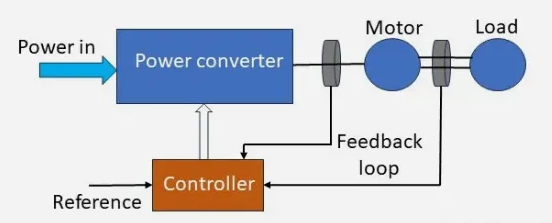
Figure 1: Overall motor control scheme

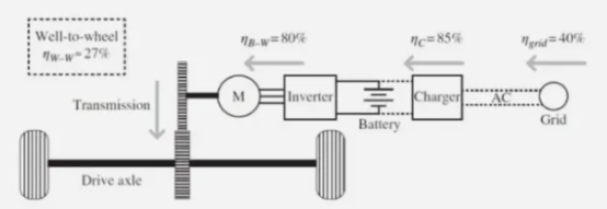
Figure 2: Electric vehicle architecture and energy flows. (Source: Hayes, J. G. and Goodarzi, G. A., 2018)
Figure 1 shows the most general scheme of a motor drive system. A power converter produces conditioned electrical energy that is used to drive the motor, whose output is mechanical energy. Figure 2 represents a typical electric vehicle architecture with an overall well-to-wheel efficiency, where all energy consumption comes from. In comparison, the well-to-wheel efficiency of an internal combustion engine is 14% and 17%, respectively, depending on whether it is based on the Otto cycle or the diesel cycle.
Electric motors can be divided into DC motors and AC motors. Each motor type consists of two main physical parts: the stator is the stationary part and the rotor is the rotating part. The main AC motor type uses three-phase alternating current to produce a rotating magnetic field, whose frequency and power are controlled by power electronic circuits that react to an accelerator.
AC and DC motors are based on similar physical principles. Speed and torque are functions of voltage, current and magnetic flux. A simple equation for an electromagnetic machine can be expressed as Tem=kI, where Tem is the torque2, k is a machine constant that depends on the magnetic material, and I is the current supplied to the machine. There is a similar relationship between the back EMF voltage (E) induced on the motor windings and the angular velocity (ωr) of the motor rotor: E = kωr. These two equations are derived from the well-known Ampere's force law and Faraday's law of induction.
Motor Requirements
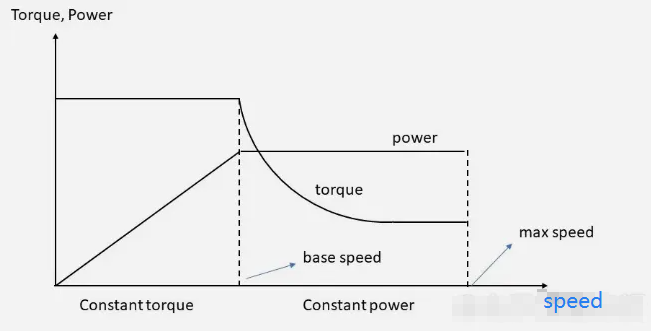
The performance of all-electric vehicles is affected by the motor specifications and is determined by the torque-speed curve and power-speed curve of the motor. High efficiency, lightweight, high power density, small size, high reliability and low cost are basic requirements. In addition, the motor is subject to different operating conditions such as frequent starting and stopping, climbing, acceleration and deceleration. This means that high torque at low speed is necessary to achieve normal starting and acceleration.
Electric vehicle motors also need to have high power at high speed and a wide speed range in the constant power area, as shown in Figure 3. The constant torque area is very important at low speed to provide a good start and overcome the slope route. The constant power area determines the maximum speed of the electric vehicle on a flat road. After reaching the basic speed, the motor reaches its rated power limit and the motor torque decreases proportionally with the square of the speed. This range is different for different types of motors, which is also a key parameter for selecting a suitable electric vehicle motor.

Figure 3: Typical speed-torque characteristics of an electric vehicle motor
Motor Type
Electric vehicle motors generally include DC motors, asynchronous motors or induction motors (IM), permanent magnet synchronous motors (PMSM), switched reluctance motors (SRM) and electrically excited synchronous motors (EESM). They all have radial flux. The flux is perpendicular to the axis of rotation. Recently, axial flux motors have attracted people's interest because they can provide more power while having a lower mass density.
DC Motor
DC motors are rugged and easy to drive. DC motors are classified into two types: brushed and brushless. Brushed DC motors are a mature technology with low cost, high low-speed torque, and simple speed control, which are important characteristics of traction motors. However, brushed DC motors are not widely used in electric vehicles due to their large size, low efficiency, and maintenance requirements due to wear of brushes and collectors. Brushed DC motors are the best choice for many uses in automobiles: windshield wipers, seat and mirror adjusters, electric steering, electronic throttle control, exhaust gas recirculation, window lifts, and electric pumps, to name a few. Brushless DC motors for electric vehicles use an electronic commutator/inverter system instead of brushes, which is more efficient. The stator coils are energized in a specific sequence by an electronic controller, which creates a rotating magnetic field that interacts with the permanent magnets on the rotor.
Asynchronous Induction Motor
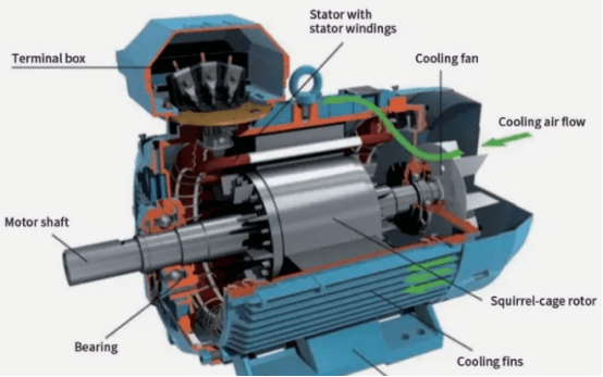
Induction motors are very common in electric vehicles due to their simple construction, high reliability even under harsh conditions, ruggedness, ease of maintenance and low cost. Induction motors can be naturally de-excited if the inverter fails, which is an important safety feature in electric vehicles. As the name implies, the rotor rotates asynchronously with the stator rotating magnetic field, which is generated by three equidistant coils with currents 120° out of phase. The rotor is mainly squirrel cage type with long bars running through it and shorted at both ends. According to Faraday's law, the stator rotating magnetic field induces voltage and current on the rotor. The induced current then interacts with the rotor magnetic field, causing it to produce torque. The disadvantages of induction motors compared to PMSM motors are slightly lower efficiency, higher heat losses on the rotor due to the induced currents, and relatively low power factor. Such motors are usually designed with multiple pole pairs to increase the frequency at a given mechanical speed, thereby reducing the size and weight of the motor.

Permanent Magnet Synchronous Motor
PMSMs have permanent magnets in their rotors. They are simple in construction, more efficient than induction motors, and have high power density. In a permanent magnet AC motor, the rotor contains one to multiple pairs of permanent magnet poles. The current fed into the stator interacts with the permanent magnets on the rotor to produce torque. The disadvantages of this motor are high cost, eddy current losses from the permanent magnets at high speeds, and reliability risks due to the possibility of magnet breakage. There are two variants of PMSM motors: surface-mounted permanent magnet (SPM) synchronous drive motors and interior permanent magnet (IPM) synchronous drive motors. IPM motors are mainly used in electric vehicles and have better performance than SPMs, but have the disadvantage of complex design.
IPM motors produce torque through two mechanisms: the interaction between the permanent magnet flux and the supply current, and the interaction between the supply current and the ferrous material, which produces reluctance torque. This occurs when a ferromagnetic object is placed in an external magnetic field, causing it to magnetize and align with the external field. The torque generated between the two magnetic fields causes the object to twist around the magnetic field lines.
Figure 5 shows the 220 PMSM produced by BorgWarner, which has a speed of 18,000 rpm and can output a torque of 250 to 450 Nm. The power range is 135 to 300 kW and the operating voltage is 300 to 800 V.
Switched Reluctance Motor
SRMs use the magnetic resistance of the rotor and stator to generate torque and control speed. The rotor consists of salient poles (magnetic poles that extend outward), while the stator contains concentrated windings. The rotor and stator are separated by an air gap, and when the motor is not rotating, the rotor poles align with the stator poles. The number of poles in the rotor and stator determines the torque and speed characteristics of the motor.
One of the main advantages of SRMs is high torque density, that is, high torque output in a small size, which is an important feature in space-constrained situations (such as electric vehicles). Another advantage of SRMs is the ability to accurately control rotor position and speed. The absence of magnets avoids mechanical force issues, so the motor can run at higher speeds. Since the phases are not connected, SRM motors can continue to operate even if one phase is disconnected. The disadvantage of this motor type is increased vibration and noise. In addition, the salient pole rotor and stator structure will produce large torque ripple.
Electrically Excited Synchronous Motor
PMSMs have the highest efficiency of all motors, but rare earth materials are a problem. Therefore, some manufacturers, such as the BMW Group and Renault Group, use hybrid motor designs, that is, synchronous motors without rare earth materials. In fact, these motors do not use permanent magnets in the rotor to generate current but use brushes and slip rings. The EESM stator generates a rotating magnetic field through alternating current. At the same time, direct current is supplied to the rotor to generate a magnetic field that is synchronized with the rotating magnetic field of the stator. The synchronous interaction between the rotor and stator magnetic fields generates torque and propels the vehicle forward. In addition, the magnetic field strength of the rotor can be varied to optimize the peak power output. According to BMW, the efficiency of this motor is as high as 93%, which is very close to that of PMSM. Despite these advantages, the brushes used in this motor must be carefully designed to obtain a sufficiently long service life. An alternative to the EESM excitation system based on a wireless power transmission system has been proposed.
Axial Flux Motor
Unlike radial flux motors, in axial flux motors, the magnetic field generated by the rotor and stator is parallel to the axis of rotation. This configuration allows for more efficient use of the magnetic flux, reducing power losses, and thus improving the overall efficiency of the motor. Quantitatively, in axial flux motors, the relationship between torque and diameter is proportional to the cube of the diameter. In contrast, in radial flux motors, torque is proportional to the square of the diameter and linearly related to length. Therefore, at the same torque, the overall size of the axial flux motor is reduced, allowing for high power density. One of its disadvantages is that it is relatively expensive to manufacture because the rotor and stator need to be precisely aligned. In addition, since the technology is still under development, its application is not yet widespread. Figure 6 shows a P400 R axial flux motor produced by YASA, a subsidiary of Mercedes-Benz.
Author: Filippo Di Giovanni
References
1. Hayes, J. G., & Goodarzi, G. A. (2018). “Electric Powertrain: Energy Systems, Power Electronics and Drives for Hybrid, Electric and Fuel Cell Vehicles.” Wiley.
2. Torque is the extension of the linear force concept to rotating bodies and can be expressed as the product of the perpendicular component of force and the distance of the applied force from the rotation axis.
3. Magnetic reluctance (R) is used in magnetic circuits and plays the same role as electrical resistance in electrical circuits. It is a measure of how much it opposes the magnetic flux (ϕ).


