1. Components of an Adaptive Air Suspension System
The adaptive air suspension system primarily consists of variable damping shock absorbers, air springs filled with compressed air, a network of sensors, electronic control units (ECUs), actuators, an air compressor, and a series of control valves.
1.1 Chassis Control Unit (CCU)
The system collects various signals from sensors and, based on pre-defined algorithms, sends commands to actuators to adjust the suspension status accordingly. In the Audi Q7, the chassis control unit integrates the software for both suspension and damper adjustment. Additionally, sensors responsible for measuring vertical acceleration, longitudinal body motion (roll), and lateral pitch rate are also integrated into this unit. It is installed at the front of the vehicle, positioned beneath the air conditioning unit and below the center console.
1.2 Accumulator
It’s primary function is to provide sufficient compressed air for lifting the vehicle’s suspension height when required.
1.3 Air Spring
The front and rear axle air springs operate on the same principle.
To maximize luggage compartment space, the rear axle air spring is equipped with an additional auxiliary air tank. This design allows for a significant reduction in the diameter of the air spring integrated into the shock absorber strut.
When the vehicle frame moves closer to the axle, the piston assembly moves downward inside the cylinder sleeve. If the current in the electromagnetic coil increases, the resulting electromagnetic force becomes stronger, causing the main damping valve to move upward. This enlarges the valve opening, reduces the oil pressure in the lower chamber, and decreases the damping force. Conversely, when the current decreases, the valve opening narrows, oil pressure rises, and the damping force increases.
1.4 Air Supply Unit
The air supply unit consists of a control unit, solenoid valve assembly, motor, and compressor. The compressor and motor form a compact driving assembly integrated with the solenoid valve body, all mounted on a single bracket. The entire unit is securely installed on the right rear side of the vehicle body.
1.5 Solenoid Valve Assembly
The solenoid valve assembly consists of five solenoid valves that connect the air supply unit to the air springs and the accumulator. A pressure sensor is integrated within the solenoid valve assembly.
2. Working Principle of Air Suspension Systems
The system continuously monitors the vehicle’s height in real-time using height sensors. When a change in vehicle height is detected, the system automatically inflates or deflates the air springs based on specific algorithms, maintaining the vehicle at the preset height and ensuring the air springs operate under optimal conditions. During the process of raising and lowering the vehicle body, the air springs undergo different extension and compression phases.
2.1 Vehicle Body Lifting (Suspension Extension) Process
When the number of occupants or load weight increases, the vehicle body height decreases. The control unit detects the height drop through sensors and opens the raise valve. Compressed air flows through the solenoid valve into the air springs, increasing their internal pressure and consequently raising the vehicle body. During the inflation process, the control unit continuously monitors the height in real-time. Once the height returns to the preset value, the solenoid valve closes. At this point, the height control valve maintains a balanced state to ensure the vehicle height remains constant.
2.2 Vehicle Body Lowering (Suspension Compression) Process
When the number of occupants or load decreases, the vehicle body height rises. The control unit detects the height increase via sensors and opens the lower valve. Air inside the air springs is released through the solenoid valve, causing a decrease in internal pressure and lowering the vehicle's body. Throughout the deflation process, the control unit continuously monitors the height. Once the height reaches the preset value, the solenoid valve closes. The height control valve then returns to a balanced state, maintaining the vehicle height at the desired level.
3. Principles of Air Suspension Adjustment
3.1 Increasing the equilibrium position using the accumulator.
Accumulator Refill: When the vehicle speed exceeds 30 km/h, the accumulator refill process is initiated. The system first activates the solenoid valve, followed by the compressor and the accumulator, as illustrated below.
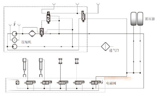
Raising the Equilibrium Position via the Accumulator (Front Axle Example)
The accumulator is primarily used during vehicle stationary and low-speed adjustment phases to improve the vehicle’s acoustic performance. Generally, the accumulator will be utilized to complete the adjustment only when its pressure exceeds the pressure in the target air spring by approximately 3 bar or more.
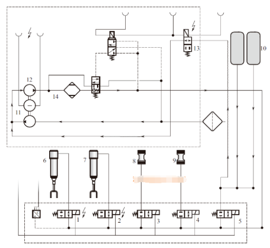
As illustrated in the pneumatic diagram below (using the front axle raising the equilibrium position as an example), solenoid valves 1 and 2 inside the solenoid valve assembly are activated while the compressor remains off (in standby mode). Compressed air flows from the accumulator through the open solenoid valves 1 and 2 into the front axle air springs.
3.2 Raising the Equilibrium Position via the Compressor
When the vehicle speed exceeds 30 km/h, pressure is primarily generated by the compressor to complete the adjustment process. To achieve this, the corresponding solenoid valves within the solenoid valve assembly are controlled, and the connection line between the compressor and the air springs is opened. As shown in the diagram below, the compressor’s boost function generates pressure, thereby raising the equilibrium position on the front axle.
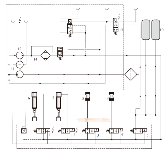
This feature belongs to the boost pressure design, enabling rapid pressure buildup when needed by utilizing the pressure stored in the accumulator. Compressed air from the accumulator is directed into the compressor’s second-stage intake further to increase the pressure present in the first stage. The boost function activates when the accumulator pressure is insufficient to complete the adjustment process (typically when pressure exceeds 5 bar). If the accumulator pressure falls below 5 bar during adjustment, the process does not pause but instead terminates directly. When solenoid valve 13 is activated, compressed air from the accumulator may additionally enter the compressor’s second-stage intake area at valve 12. Before leaving the compressor, the compressed air passes through an air dryer (14), which removes moisture from the air.
3.3 Lowering the Equilibrium Position (Rear Axle Example)
As shown in the diagram below, solenoid valves 1 through 4 within the solenoid valve block are activated to open the connection lines between the compressor and the air springs. To release the compressed air from the air springs, the pneumatic changeover valve must be opened. This is achieved by activating solenoid valve 12, which allows pressure to be applied to the control port of the pneumatic changeover valve, switching it to the open position.
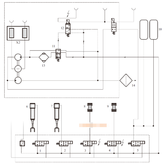
The air flows through the valve and is discharged via the intake/exhaust port. At this stage, the compressed air passes through the air dryer, which removes moisture from the airflow.
HONEST Automation has extensive experience with proven applications in automotive air suspension motor assembly line. We offer both semi-automatic and fully automatic solutions for motor assembly and coil winding. Feel free to contact us online to get a customized solution tailored to your production needs.