The stator of a new energy vehicle motor—as the stationary part of the electric drive system—is typically composed of a laminated stator core, stator windings, insulation materials, and auxiliary components such as lead wires. Its primary role is to generate a rotating magnetic field when the motor operates, which interacts with the rotor to convert electrical energy into mechanical energy, ultimately driving the vehicle forward.
In modern EV motors, advanced winding technologies such as continuous hairpin winding and wave winding are increasingly adopted to improve efficiency, power density, and manufacturing consistency. Especially, the use of continuous hairpin structures allows for better thermal management, reduced copper losses, and enhanced automation in stator assembly.
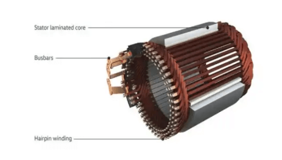
In the electric motor industry, the commonly discussed terms "flat wire" and "round wire" refer to different types of stator windings. Round wire motors typically use multiple thin circular conductors, while flat wire motors—also known as hairpin motors—use rectangular conductors for the windings.
The rectangular shape of flat wires is better suited to the geometry of stator slots, allowing for a slot fill factor of over 70%. In contrast, round wire motors often achieve less than 50%. This means flat wire motors can accommodate more conductor material in the same or even smaller motor volume, resulting in higher power density.
Modern EV motors increasingly adopt continuous hairpin winding and wave winding technologies to fully leverage the advantages of flat wire designs. These approaches enhance thermal performance, reduce losses, and improve overall system efficiency, making continuous hairpin configurations a mainstream choice in next-generation electric motor manufacturing.

As new energy vehicle (NEV) technology continues to evolve, so too does the design of electric drive stators. Changes in winding structure—particularly the adoption of continuous hairpin winding and wave winding techniques—have significantly increased slot fill factors and overall motor performance.
However, these advancements also bring higher demands for thermal management. To ensure long-term, high-efficiency operation, cooling strategies must evolve in parallel with motor design. Today, various cooling solutions are being developed and optimized to meet the needs of high-density, high-power stator systems built with continuous hairpin technologies.
Let’s take a closer look at how stator design is advancing and where it's headed in the future of electric mobility.
The transition of stator windings from round wire to flat wire is not simply a change in the shape of the conductor, but rather a fundamental transformation involving motor design, manufacturing processes, and performance optimization. Hairpin winding can be structurally classified into Hairpin, I-pin, W-pin, and the recently popular X pin, N pin, and Mini pin, which are all improvements based on the Hairpin and I-pin structures.

At present, the most common form of flat wire winding is the Hairpin type, which accounts for nearly 90% of the hairpin solutions available on the market. The overall process involves pre-forming the wire, inserting it into the stator slots, and then performing single-sided welding. Its key feature is that only one end needs to be welded.
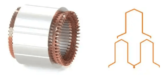
The I-pin process involves directly inserting the wire followed by double-sided welding. Currently, it is only being used by United Automotive Electronic Systems. Since both ends require welding, the number of weld points is doubled compared to the Hairpin process, and the winding end length is also slightly longer. Coating requirements are also doubled. However, the slot fill factor of the I-pin is higher than that of the Hairpin.
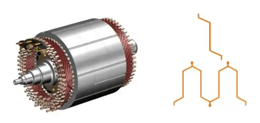
The winding end of the W-pin is the shortest among these three flat wire types and does not require processes such as enamel stripping, cutting, or welding. The main players using this technology are BorgWarner and NIO. Its key feature is that one coil is connected in series with the coil under the adjacent like magnetic pole, characterized by a synthesized pitch representing the continuous pattern of the wave winding. This approach effectively reduces the end winding length, thereby decreasing the radial dimension of the motor.
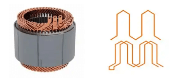
Naturally, the W-pin process is also the most challenging. The main difficulty lies in automatic wire insertion. Unlike Hair-pin, which can be inserted axially, W-pin cannot be inserted axially and must be inserted radially. Depending on the insertion direction, it can be divided into inner-diameter insertion and outer-diameter insertion.
For inner-diameter insertion, the W-pin is compressed to align concentrically with the stator core and then expanded using a fixture to enter the stator slot. This method requires the slot opening to be wider than the slot base. Compared to Hairpin technology, the slot fill factor is reduced by about 10-15%, and there is also a risk of magnetic leakage. Magnetic leakage is one of the biggest disadvantages of the W-pin. Currently, efforts to reduce leakage mainly focus on optimizing the stator core design, such as using self-bonded cores instead of welded cores.
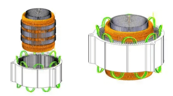
For outer-diameter insertion, the stator core is cut along the slot bottom, dividing it into an inner and outer ring. The copper wire is pressed from the outside of the core into the inner ring, and then the outer ring is welded back to the inner ring. This method features copper wire slots similar to those in Hairpin technology, where the slot opening is narrower than the slot bottom, which helps improve both slot fill factor and reduce magnetic leakage.
However, since welding is limited to the core surface, the structural strength of the stator core poses a challenge. Currently, the inner-diameter insertion method is more commonly used, while the outer-diameter insertion approach is relatively rare.
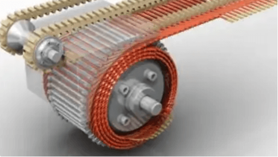
The X-pin is an improved version based on the Hair-pin and I-pin designs. United Automotive Electronics' solution mainly reduces the height of the straight section of the I-pin. The name "X-pin" comes from the overlapping pattern of the weld points. After the winding is formed, the weld trajectories viewed from both the front and top angles intersect each other in an "X" shape. Additionally, the letter "X" is a homophone of the Chinese word meaning "small," referring to the compact winding envelope. Therefore, this winding form was named "X-pin" during its development.

BorgWarner has upgraded its product from the original Hair-pin to the X-pin process. While the overall wire insertion end dimensions remain the same as Hairpin, the X-pin design reduces the size of the welded end. Most of the commonly used X-pin solutions in China are also based on modifications of the Hair-pin, such as those by Shanghai Electric Drive, Aion, and Hongqi.
The core challenges of the X-pin solution mainly lie in the winding welding process and the design of tooling fixtures. Additionally, it must meet high-voltage insulation requirements of up to 800V. For X-pin to be practically applied, insulation standards must be met, which requires a creepage distance of 10-12mm on the flat wire winding. Heat effects during welding also need to be carefully controlled to avoid damaging the enamel coating.
Of course, the short-pin designs are not limited to just the X-pin type. For example, Huayu’s Umini-pin and Shanghai Electric Drive’s N-pin have also been developed to reduce winding end height.
Beyond winding structure design, there are various winding methods based on the conductor crossing patterns. For instance, Hair-pin commonly uses left-to-right crossing or same-layer crossing; I-pin includes Z-type and I-type crossings; W-pin involves segmented wave winding and integral wave winding; and there are also designs focusing on eliminating circulating currents within the winding.
Is more direct cooling better for the stator?
During motor operation, heat is generated due to resistive losses (copper losses) from current flowing through the windings and iron losses caused by changes in magnetic flux. The winding end regions of the motor are usually located in non-active areas, so they lack direct cooling paths and tend to accumulate heat. Additionally, the insulation layers at the winding ends are relatively thick and have poor thermal conductivity, making these areas prone to becoming hotspots.
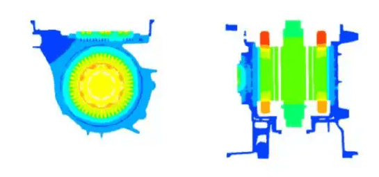
The conventional water cooling method uses a water jacket wrapped around the stator core. When the coolant flows through the channels inside the water jacket, heat generated by the windings—especially under low-speed conditions where heat generation is highest—is first conducted through the stator core to the water jacket, and then carried away by the coolant. However, when the motor operates at medium to low speeds, the heat generated in the stator increases significantly, with the main heat sources being losses in the stator windings and the iron core.
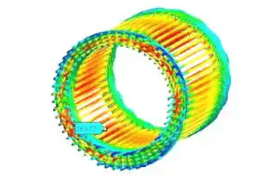
Traditional water cooling methods have certain limitations when dealing with heat generated by motor windings, especially because local hotspots can form along the thermal conduction path between the insulated stator core and the housing, which reduces cooling efficiency. As an alternative, oil cooling technology effectively addresses these issues and demonstrates higher cooling efficiency in continuous-duty motors.
Oil cooling can directly spray the cooling medium onto the winding ends or other heat-generating areas, achieving direct contact with the heat source. This direct contact significantly lowers thermal resistance and improves heat dissipation. Unlike water cooling, oil cooling does not interfere with the motor's magnetic circuit because oil has minimal impact on magnetic fields, which is crucial for maintaining electromagnetic performance. Additionally, a major advantage of oil cooling over water cooling is its ability to increase the motor’s continuous power output.
Currently, there are two common oil cooling methods for stators: oil pipes/oil rings and oil grooves machined into the core. The oil pipe spraying design uses separate oil pipes to spray directly onto the winding ends for cooling, with oil rings primarily used to adjust the spray angle. Neither requires machining oil grooves in the stator core, making them simpler and less costly.
On the other hand, machining oil grooves in the stator core allows oil to flow through the core, enabling simultaneous oil cooling of both the winding ends and the interior. This requires designing an oil circuit within the stator and machining grooves into the original stator core. Different manufacturers have varying designs for the oil flow paths and spray angles.
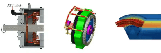
Ultimately, both of these methods are variations of spray cooling for the windings. Technically, there is a certain iterative relationship between them, but in practical applications, the relationship is not strictly sequential. Beyond cost considerations, these two approaches can actually complement each other. Some companies combine both methods—for example, using stator core oil grooves together with oil pipes for cooling. In some cases, oil pipes provide radial, all-around spraying, while in others, the cooling fluid is sprayed onto the stator core surface via oil pipes to ensure effective heat dissipation.
Future Trends
The overall future trend for stators revolves around lightweight design, low cost, high efficiency, as well as policy support and market demand. To meet the needs of new energy vehicles for lighter and more compact motors, stator designs will increasingly focus on compactness. By optimizing winding structures and manufacturing processes, reducing end winding length and weld points, more efficient energy conversion and a smaller motor size can be achieved. Additionally, the electric drive technology roadmap 3.0 emphasizes requirements for higher power density and efficiency zones, making the reduction of winding end length and improvement of slot fill factor clear technological trends for the future.
On the materials side, high-performance conductive materials such as low-resistance copper or aluminum wires will be used to reduce winding resistance losses and increase motor output power. Furthermore, to enhance cooling performance, new cooling media with higher thermal conductivity, lower viscosity, and broader operating temperature ranges are likely to be developed and applied in the future.
HONEST Automation has delivered a range of winding and assembly equipment for Hairpin, X-pin, and Mini-pin motors, supporting prototype development and small-batch production. If you are seeking automated solutions for automotive motor manufacturing, please feel free to contact us via online inquiry or email. Our team of experts will respond promptly to provide you with professional technical support and services.


