1. Electric Drive System
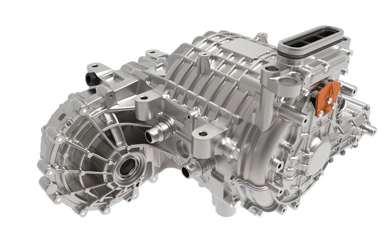
The electric drive system is the core of an electric vehicle, generally consisting of a motor, controller, and gearbox. It is responsible for converting electrical energy into mechanical energy to propel the vehicle. The electric drive system plays a role similar to that of the "engine, ECU (Electronic Control Unit), and transmission" in internal combustion engine vehicles and significantly impacts key performance indicators of new energy vehicles, such as power, efficiency, comfort, and safety. Its structural design directly affects the layout of the vehicle’s drive system. Currently, the integration of the motor, controller (MCU, Motor Control Unit), and gearbox into a single unit, known as the three-in-one electric drive system, has become the mainstream development trend for pure electric vehicle drive systems due to its advantages in lightweight design, space savings, and low cost.

01 Drive Motor Assembly: Converts electrical energy from the power battery into rotational mechanical energy, serving as the power output source.
02 Controller Assembly: Controls the motor’s operating state (forward or reverse) based on commands from the VCU. Utilizing power semiconductor-based hardware and software design, it enables real-time control of the drive motor’s operation while continuously enhancing additional control functions.
03 Reducer: Uses a gear set to reduce output speed and increase output torque, ensuring the electric drive system operates consistently within a high-efficiency range.
2. Motor
The motor, specifically the main drive motor in new energy vehicles (NEVs), is responsible for all functions related to vehicle movement. In pure electric vehicles, the drive motor is required to perform dual functions—as both a motor and a generator. During normal driving, it acts primarily as a motor, converting electrical energy into mechanical energy. During deceleration or downhill coasting, it functions as a generator, converting the wheels’ kinetic energy back into electrical energy through regenerative braking.
The selection of the drive motor must be based on its load characteristics. An analysis of vehicle driving conditions shows that when starting or climbing hills, the vehicle requires high starting torque and a significant short-term overload capacity. It also demands a wide speed adjustment range and optimal speed control characteristics—that is, constant torque output at low speeds during start-up and high power output at higher speeds.
The drive system, consisting of the drive motor and motor controller, is the most critical component in a pure electric vehicle. The vehicle’s performance largely depends on the type and capabilities of this drive system, as it directly affects key performance indicators such as driving speed under various conditions, acceleration, climbing ability, and energy conversion efficiency.
2.1 Main Types of Motors and Their Working Principles
(1) Permanent Magnet Brushless DC Motor (BLDC Motor)
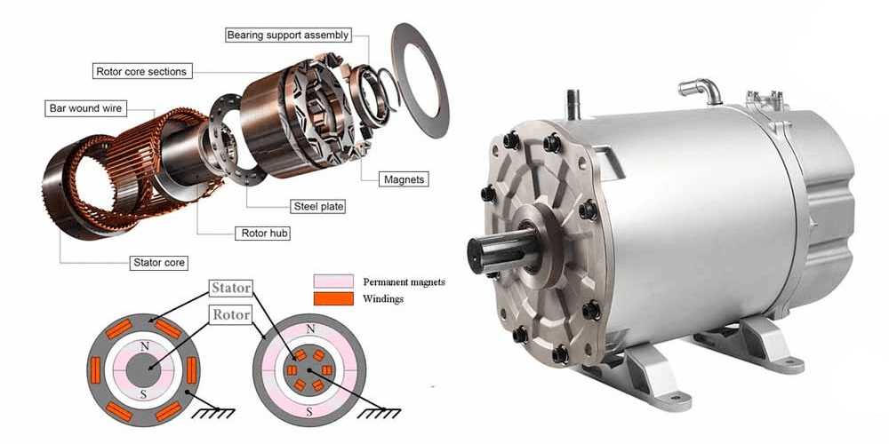
The permanent magnet brushless DC motor mainly consists of three parts: the motor body, the electronic commutator, and the rotor position sensor.
The motor body is composed of a stator and a permanent magnet rotor. The electronic commutator, which consists of power switches and a position signal processing circuit, is primarily responsible for controlling the sequence and timing of current supplied to the stator windings. The rotor position sensor plays a crucial role in detecting the magnetic pole position of the rotor and provides accurate commutation signals to the power switch circuit by converting the rotor position into electrical signals. These signals are processed by the signal processing circuit to control the switching of current in the stator windings.
The working principle of a permanent magnet brushless DC motor is essentially the same as that of a brushed DC motor. It uses signals from the rotor position sensor to control the electronic commutation circuit, which drives the inverter’s power switching devices. This enables the armature windings to be energized in sequence, generating a stepping rotating magnetic field in the stator that drives the rotor’s rotation. As the rotor turns, the position sensor continuously sends updated signals to adjust the energizing state of the armature windings, ensuring that the direction of current in the conductor under a given magnetic pole remains constant. This maintains continuous motor operation.
(2) Permanent Magnet Brushed DC Motor
In a brushed motor, fixed main magnetic poles and brushes are installed on the stator, while the rotor contains the armature winding and a commutator. Electrical energy from the DC power source enters the armature winding through the brushes and commutator, generating armature current. The magnetic field produced by the armature current interacts with the main magnetic field, generating electromagnetic torque that drives the motor to rotate and power a load.
Due to the presence of brushes and a commutator, brushed motors have a more complex structure, lower reliability, more frequent failures, higher maintenance requirements, and shorter lifespans. Additionally, commutation sparks can easily generate electromagnetic interference.
(3) AC Induction Motor
AC induction motors, also known as three-phase asynchronous motors, have a basic structure as shown below. When connected to a three-phase AC power supply, the stator windings produce a three-phase magnetomotive force (stator rotating magnetomotive force), which generates a rotating magnetic field. This rotating magnetic field cuts across the rotor windings, inducing a current in the rotor windings (which form a closed circuit).
Through the relative motion between the stator's rotating magnetic field and the rotor windings, the rotor windings cut through magnetic flux lines, inducing an electromotive force (EMF). This EMF generates an induced current in the rotor windings. The interaction between the induced current and the magnetic field produces electromagnetic torque, causing the rotor to rotate.
As the rotor speed gradually approaches the synchronous speed, the induced current decreases, resulting in a corresponding reduction in electromagnetic torque. When an induction motor operates in motor mode, the rotor speed is always slightly less than the synchronous speed.
(4) Permanent Magnet Synchronous Motor (PMSM)
A permanent magnet synchronous motor consists of components such as the stator, rotor, and end caps. The stator is similar to that of a conventional induction motor and typically uses a laminated structure to reduce core losses during operation. The rotor can be constructed as a solid core or made from laminated steel sheets. The armature windings may use concentrated full-pitch windings, distributed short-pitch windings, or unconventional winding configurations.

Similar to an AC induction motor, when three-phase sinusoidal alternating current is applied to the stator windings of a PMSM, a rotating magnetic field is generated. This rotating magnetic field interacts with the magnetic field of the permanent magnets on the rotor, generating electromagnetic torque. As a result, the rotor rotates synchronously with the stator’s rotating magnetic field—hence the name "synchronous motor."
For a given model of a synchronous motor, its rotational speed is determined solely by the frequency of the power supply. Currently, PMSMs are widely adopted in automotive applications due to their high efficiency and performance.
2.2 Layout of the Drive System in Pure Electric Vehicles
Integrated Motor–Drive Axle Configuration
This type of drive system layout is similar to that of an internal combustion engine (ICE) vehicle with a transversely mounted engine and front-wheel drive. In this configuration, the electric motor, fixed-ratio reducer, and differential are integrated into a single unit, with two half-shafts connected to drive the wheels.
There are two main types of integrated motor–drive axle drive system layouts:
Coaxial Type: where the motor and the axle share the same central axis.
Dual-Axle (Parallel) Type: where the motor is mounted parallel to the axle, and power is transmitted through a gear set.
This layout offers compactness and is well-suited for front- or rear-wheel-drive applications in electric vehicles.
Electric Motor–Drive Axle Combined Drive Mode
The electric motor–drive axle combined drive system mainly consists of an electric motor, drive axle, and electronic control system. The electric motor acts as the power source of the vehicle, directly driving the drive axle to provide propulsion. The drive axle, as a critical part of the transmission system, transmits the motor’s power to the wheels. Meanwhile, the electronic control system manages the working state of both the motor and the drive axle, enabling intelligent control and coordination.
This drive mode allows the electric motor to demonstrate its performance advantages fully. Since the drive motor powers the wheels directly, traditional mechanical transmission components such as gearboxes are no longer needed. This leads to a more efficient energy conversion process, enhancing both vehicle acceleration and power output capabilities.
The electric motor–drive axle combined drive mode also offers higher reliability. Conventional automotive drivetrains involve multiple mechanical components such as drive shafts and universal joints, which are prone to failure. In contrast, this simplified setup reduces mechanical complexity, lowering maintenance costs and minimizing downtime caused by mechanical failures.
Additionally, this drive mode enables regenerative braking. During deceleration or braking, the motor can function as a generator, converting kinetic energy back into electrical energy and storing it in the battery. This improves the overall energy efficiency and extends the vehicle's driving range.
In-Wheel Motor Distributed Drive Mode
The distributed drive mode refers to installing electric motors directly at each wheel of the vehicle, where each motor is independently controlled to drive and brake its corresponding wheel. This configuration allows for a more balanced distribution of the vehicle's center of gravity, significantly reducing rolling inertia and thereby enhancing driving safety.
Moreover, because each motor operates independently, the system can dynamically adjust the rotational speed of each wheel in real time. This enables precise control over the vehicle’s dynamic stability. As a result, the distributed drive mode maximizes both vehicle stability and handling performance, improving road grip and steering response.
3. Motor Controller
In electric vehicles, the Motor Control Unit (MCU) serves as the central control unit of the powertrain, responsible for managing the drive motor. It receives control signals from the vehicle control unit (VCU) and input devices (such as the brake pedal, accelerator pedal, and gear selector), and converts the direct current (DC) from the power battery into alternating current (AC) required by the drive motor. By regulating the motor’s voltage and current, the MCU controls the motor’s speed, torque, and direction, enabling functions such as vehicle start-up, forward and reverse motion, climbing capability, and overall driving dynamics. Additionally, the MCU can manage the battery's output during braking, helping to recover and store some of the braking energy back into the power battery.
Motor controllers in new energy vehicles are typically divided into two main categories: main controllers and auxiliary controllers. The main controller manages the traction motor, converting the DC power from the battery into AC power for the motor, and controls motor torque, speed, and direction. The auxiliary controller regulates AC output to control the torque and speed of auxiliary motors, such as those used for electric power steering pumps, air compressors, air conditioning compressors, BSG motors, and ISG motors.
4. Reducer
The primary function of a gearbox (reducer) is to reduce the speed, increase the output torque, and decrease the load inertia.
A gearbox mainly consists of a gearbox housing, internal gears, and bearings. The motor output shaft connects to the input shaft of the gearbox inside the housing, and the gears transmit the high-speed, low-torque input from the motor to the output shaft through meshing. Due to the gear ratio between the output shaft gears, the motor's output speed decreases, but at the same time, the output torque increases accordingly.
The working principle involves the motor's output speed being input to the driving shaft, which rotates a small gear. This small gear drives a larger gear, and because the larger gear has more teeth than the smaller one, its rotational speed is slower. The output from the larger gear’s shaft results in a reduced output speed. The gearbox is an independent, closed transmission device between the prime mover and the working machine. It is a relatively precise mechanical component, and its purpose is to reduce speed and increase torque.


