Stator coil winding is one of the most critical processes in BLDC motor manufacturing. The quality and precision of the winding process directly influence the motor's power density, efficiency, and long-term operational reliability. This article provides a systematic overview of the standard BLDC stator winding process, covering equipment selection, winding methods, key manufacturing steps, and quality control practices.
1. Winding Equipment Selection and Application
The choice of winding equipment depends primarily on the stator slot orientation and structural design. In BLDC motor manufacturing, stator winding machines are generally classified into two categories: external flyer winding machines and internal needle winding machines.
External Flyer Winding Machine
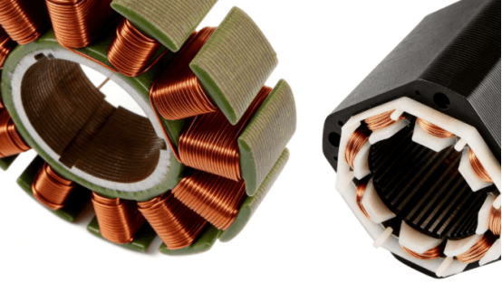
External flyer winding machines are designed for outer-rotor stators with outward-facing slots, such as those used in RC motors, self-balancing scooter motors, and household appliance fan motors. During the winding process, a high-speed flyer rotates to guide the magnet wire around the stator teeth. Flyer speeds typically range from 2,000 to 5,000 rpm, providing high productivity and making this solution ideal for high-volume standardized manufacturing.
Internal Needle Winding Machine
Internal needle winding machines are suitable for inner-rotor stators with inward-facing slots, including electric power tools, water pump motors, EV traction motors, and servo motors. A servo-driven winding needle reciprocates vertically while the tooling indexes horizontally to achieve accurate layer-by-layer wire placement. Standard machines typically support wire diameters from 0.1 mm to 1.5 mm, while heavy-duty models can accommodate wire sizes up to 2.0 mm.
To ensure consistent winding quality, the machine's critical components—including servo motors, electronic wire tension controllers, and winding needles—must deliver high responsiveness and minimal backlash. High-performance components help maintain wire tension fluctuations within ±0.05 N and wire placement accuracy better than ±0.03 mm, effectively preventing common winding defects such as wire crossover, skipped turns, and enamel insulation damage.
2. Selecting the Appropriate Stator Winding Configuration
BLDC motor stators are primarily wound using one of two winding configurations: concentrated windings or distributed windings. The optimal choice depends on the motor's performance requirements and intended application.
Concentrated Windings
In a concentrated winding, each coil is wound around a single stator tooth, which is why this configuration is also known as a tooth winding. Concentrated windings feature a compact structure, short end turns, and reduced copper losses, making them ideal for applications requiring high torque at relatively low speeds. Typical examples include drone propulsion motors and robotic joint motors. This winding configuration is the standard choice for fractional-slot concentrated winding (FSCW) motors.
Distributed Windings
In a distributed winding, each coil spans multiple stator slots, with the coil pitch typically approaching the pole pitch. For example, in a 24-slot, 8-pole motor, a typical coil pitch may range from slots 1–4, spanning three slots. Distributed windings produce a more sinusoidal magnetic field and back-EMF waveform while minimizing harmonic distortion. As a result, they are widely used in high-speed, low-noise, and low-vibration applications such as high-speed blower motors, servo spindle motors, and EV traction motors.
3. Key Steps in the Stator Winding Process
3.1 Stator Clamping and Tooling Setup
The stator core is securely mounted on the winding machine fixture before production begins. The tooling, wire guide plates, and winding needle are then precisely aligned, with a positioning accuracy of ±0.02 mm. After setup, a dry run is performed to verify that the needle trajectory perfectly matches the stator slot geometry, preventing common winding defects such as wire crossover, enamel insulation damage, and wire breakage.
3.2 Parameter Setup and First Article Verification
The operator enters the winding parameters into the control system, including the number of turns, coil pitch, winding speed (typically 500–1,500 rpm for needle winding), and wire tension profile before performing a trial winding.
After the first stator is completed, three critical inspections should be carried out:
Coil Turn Count Verification: The allowable deviation should be within ±1 turn. For precision coils with a small number of turns, zero deviation may be required.
Three-Phase DC Resistance Test: The resistance imbalance between the three phases should not exceed ±2%.
Insulation Withstand Voltage Test (Hi-Pot Test): The test voltage should comply with 2Uₙ + 1000 V (where Uₙ is the rated voltage), with a minimum test voltage of 1000 V. No dielectric breakdown or flashover is permitted.
3.3 Automatic Winding and Precision Wire Placement
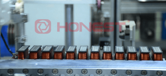
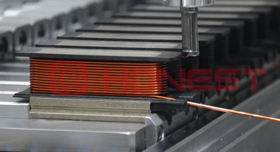
Once the parameters are confirmed, the winding machine automatically performs winding, wire placement, lead indexing, and other programmed operations. For multilayer windings, polyester film or DMD insulation paper should be inserted between layers to enhance interlayer insulation. The wire must be evenly distributed without crossover or overlap to minimize the risk of inter-turn short circuits. Throughout the winding process, wire tension should be continuously monitored to ensure consistent coil tightness and winding quality.
3.4 Lead Securing, Electrical Connections, and Insulation Treatment
After winding is completed, the lead wires and crossover wires are secured using high-temperature cable ties or self-adhesive insulating tape. The three-phase windings are then interconnected, and the coil end turns are formed to meet the specified dimensional requirements. Additional insulation paper is applied around the slot openings and coil end regions to reinforce electrical insulation.
The final step is varnish impregnation. Vacuum Pressure Impregnation (VPI) enables the insulating varnish to fully penetrate and cure throughout the winding, increasing the mechanical strength of the coil assembly by 20%–30% while significantly improving heat dissipation, moisture resistance, and long-term environmental durability.
4. Quality Control Best Practices
Winding Symmetry and Phase Connections
The three-phase windings must be symmetrically distributed with a 120° electrical phase displacement and connected with the correct phase polarity. Proper winding symmetry minimizes torque ripple, magnetic field imbalance, and unwanted vibration during motor operation.
Electrical Performance Testing
Each completed stator should undergo comprehensive electrical testing, including:
DC resistance measurement
Inductance measurement
Insulation resistance test (minimum 1 MΩ at room temperature using a 500 V or 1000 V megohmmeter)
Inter-turn surge withstand test to verify that there are no inter-turn short circuits or insulation weak points.
Visual and Dimensional Inspection
Inspect the completed winding to ensure that the coil end turns are neat and uniform, with no wire crossover, enamel insulation damage, or stator core deformation. The coil end-turn height and outside diameter should comply with the specified dimensional tolerances.
Environmental Reliability Verification
For stators used in harsh operating environments—such as outdoor water pumps and garden power equipment—the winding assembly should pass a 48-hour Neutral Salt Spray (NSS) Test to verify the corrosion resistance of both the insulation system and the impregnating varnish.
By optimizing machine configuration, refining winding parameters, and implementing comprehensive quality control procedures, manufacturers can consistently achieve a first-pass yield (FPY) exceeding 99.5%, providing a solid foundation for high-efficiency, low-noise, and long-life BLDC motors.
HONEST Automation: High-Precision BLDC Stator Winding Solutions
As a leading provider of motor winding automation systems, HONEST Automation has specialized in stator winding technology for many years. We offer a complete portfolio of high-precision flyer winding and needle winding machines, designed to meet the manufacturing requirements of a wide range of stator applications.
Powered by our self-developed intelligent control system, HONEST winding equipment delivers exceptional accuracy, stability, and production efficiency for five key industries: humanoid robot joint motors, Heavy-lift drone motors, Medical equipment motors, Power tool motors, and automotive motors.
Our advanced winding solutions help motor manufacturers improve productivity, enhance product quality, and accelerate the transition to intelligent, automated production.
Contact HONEST Automation today to request our product catalog, discuss a customized winding solution, or receive a competitive quotation.